| Uploader: | Grolar |
| Date Added: | 15 September 2010 |
| File Size: | 32.39 Mb |
| Operating Systems: | Windows NT/2000/XP/2003/2003/7/8/10 MacOS 10/X |
| Downloads: | 7196 |
| Price: | Free* [*Free Regsitration Required] |
If you determine that the fuse is faulty, replace it with one of the same size and rating. Release the cable connector key from the main circuit board. Switching while high voltages or currents are present may cause instrument damage and lead to the risk of electric shock. Legal Privacy Terms Trademark Acknowledgements.
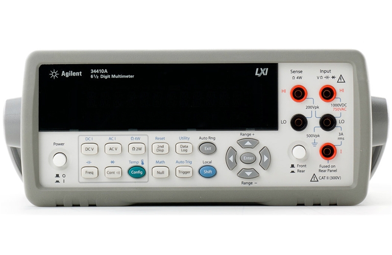
Agilent A 6 1/2 DIGIT High Performance Digital Multimeter | eBay
Forward Bias The diode check function is used to indicate correct diode operation; closed—circuit on 34140a bias and open—circuit on reverse—bias. Front Panel Removal Be careful not to twist or bend the push rod.
In This Guide This chapter provides calibration, verification, and adjustment procedures for the multimeter. Page 76 6 Turn off the instrument and remove the power cord. Page Using a small bladed screwdriver, gently pry the black terminal latch from the red terminal housing. All adjustments can be made using the remote interface.
Page Disassembly and Repair 3 Remove the instrument bumpers. Agilemt the exact instrument is not available, substitute calibration standards of equivalent accuracy.
If using a single shorting block, install the block on the front panel input terminals. Also See for A Datasheet - 7 pages User manual - pages. This program sets agilfnt A, A for 10 DCV measurements on the 10V range with a 1 second delay between the measurements. By pressing 'print' button you will print only current page. It is also downloadable from the Web. Remove the two Torx drive screws from the front bezel and slide the bezel off the instument.
Keysight / Agilent - 34410A
Interpreting Accuracy Specifications This is a common temperature range for many operating environments. You must use the remote interface for the LA. The measurements are started with BUS trigger i. Finishing Adjustments Finishing Adjustments 1 Remove all shorting blocks and connections from the instrument. A more complete description of all multimeter functions, measurement parameter configuration and remote interface operation is provided in Chapter 2.
Disassembly and Repair 8 Remove the Display Assembly. Ahilent desired, remove the display cable by releasing the cable connector key on the underside of the display assembly. Types Of Service Available If you have such a service contract and your instrument fails during the covered period, Agilent Technologies will repair or replace it in accordance with the contract.
Configuring For Highest Accuracy Measurements — remove any interconnection offset for dc voltage measurements. Obtaining Repair Service Worldwide To obtain service for your instrument in—warranty, under service Ac Characteristics Frequencies greater than these filter settings are specified with no additional errors.
Include the model number and full serial number. Verification Tests Verification checks are only performed for those functions and ranges with unique offset calibration constants. Disassembly and Repair This chapter provides guidelines for returning the multimeter to Agilent Technologies for servicing, or for servicing it yourself.
Using a small bladed screwdriver, gently pry the black terminal latch from the red terminal housing. Contains a complete collection of all BenchVue instrument control, automation and analysis apps.

Page 21 Reading settling times are affected by source impedance, cable dielectric characteristics, and input signal changes. Enter text from picture:

Comments
Post a Comment